Delrin Coupling Chain
#40 - 1/2" Pitch
| Stock No. | Description | Wt. Lbs. |
| 03004001 03004050 |
D-40 Cpl. Chain: 10' Box D-40 Cpl. Chain: 50' Box | 3.42 17.10 |
Fits any standard #40 Roller Chain Sprocket.
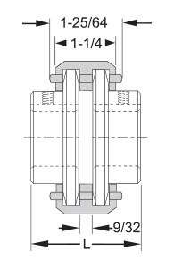
Approximate "L" Dimensions:
- Welded Sprockets over 24 teeth = 2-1/4"
- Solid Sprockets under 20 teeth = 2"
- Solid Sprockets over 20 teeth = 2-1/4"
- QD Sprockets with JA hub = 2-1/8"
- QD Sprocket with SH hub = 2-3/4"
Delrin Chain Couplings can be used in a wide range of rugged conditions:
- Temperatures from –20° to +150° F.
- Angular misalignment of 1° (10T - 19T), 1/2° (20T - 24T)
- Parallel misalignment of .005 inches.
- Total end float of .060 inches..
HP Ratings for Even Load, Non-Reversing Applications*
HP = Torque (Lb. Ft.) x RPM
5252
| No. Teeth | Overall Dia. | 100 RPM Torque (Lb./Ft.) |
Revolutions Per Minute | |||||||||||||||||
| 100 | 200 | 300 | 400 | 500 | 600 | 700 | 800 | 900 | 1200 | 1500 | 1800 | 2000 | 2500 | 3000 | 3500 | 4000 | 5000 | |||
| 10 | 2.06 | 18.90 | .36 | .71 | 1.07 | 1.42 | 1.78 | 1.99 | 2.18 | 2.36 | 2.54 | 3.03 | 3.49 | 3.92 | 4.20 | 4.85 | 5.48 | 6.20 | 6.65 | 7.80 |
| 12 | 2.37 | 26.80 | .51 | 1.02 | 1.53 | 2.04 | 2.55 | 2.85 | 3.12 | 3.38 | 3.64 | 4.35 | 5.00 | 5.60 | 6.10 | 6.95 | 7.85 | 8.90 | 9.55 | 11.20 |
| 14 | 2.69 | 36.30 | .69 | 1.38 | 2.08 | 2.77 | 3.46 | 3.86 | 4.24 | 4.58 | 4.94 | 5.89 | 6.78 | 7.61 | 8.16 | 9.42 | 10.60 | 12.20 | 12.90 | 15.10 |
| 16 | 3.00 | 47.40 | .90 | 1.80 | 2.71 | 3.61 | 4.51 | 5.04 | 5.51 | 5.98 | 6.43 | 7.68 | 8.84 | 9.92 | 10.60 | 12.30 | 13.90 | 15.70 | 16.90 | |
| 18 | 3.32 | 60.00 | 1.14 | 2.28 | 3.43 | 4.57 | 5.71 | 6.36 | 6.97 | 7.50 | 8.13 | 9.70 | 11.20 | 12.50 | 13.40 | 15.50 | 17.50 | 19.90 | 21.30 | |
| 20 | 3.64 | 74.10 | 1.41 | 2.82 | 4.22 | 5.63 | 7.04 | 7.85 | 8.60 | 9.33 | 10.00 | 12.00 | 13.80 | 15.50 | 16.60 | 19.20 | 21.60 | 24.60 | ||
| 22 | 3.96 | 89.30 | 1.70 | 3.40 | 5.10 | 6.80 | 8.50 | 9.50 | 10.40 | 11.30 | 12.10 | 14.50 | 16.60 | 18.70 | 20.00 | 23.20 | 26.20 | 29.60 | ||
| 24 | 4.27 | 106.00 | 2.02 | 4.04 | 6.06 | 8.08 | 10.10 | 11.30 | 12.40 | 13.40 | 14.40 | 17.30 | 19.80 | 22.30 | 23.90 | 27.60 | 31.20 | |||
| 26 | 4.59 | 125.00 | 2.38 | 4.76 | 7.14 | 9.52 | 11.90 | 13.20 | 14.50 | 15.70 | 16.90 | 20.20 | 23.20 | 26.10 | 28.00 | 32.30 | 36.40 | |||
| 28 | 4.91 | 145.00 | 2.76 | 5.52 | 8.28 | 11.04 | 13.80 | 15.40 | 16.80 | 18.20 | 19.60 | 23.40 | 27.00 | 30.20 | 32.40 | 37.40 | ||||
| 30 | 5.23 | 166.00 | 3.16 | 6.32 | 9.48 | 12.64 | 15.80 | 17.60 | 19.80 | 21.00 | 22.50 | 26.90 | 30.90 | 34.80 | 37.20 | 43.00 | ||||
*Use 1.5 service factor for uneven load, non-reversing applications. Use 2 service factor for heavy shock, reversing applications.
Sprocket Mounting:
- Position sprockets (coupling halves) to allow a gap between sprocket as indicated.
- Align the shafts as accurately as possible to obtain the longest service life from the coupling.
- Angular Alignment: Coupling will tolerate a maximum of 1° angular misalignment, but for optimum life, a maximum of 1/2° is recommended. Angular alignment is checked by keeping both shafts stationary and taking a measurement with a feeler gauge at 12:00, 3:00, 6:00 and 9:00. The difference between 12:00 and 6:00 will give the error in alignment in the vertical plane. Likewise, the difference between 3:00 and 9:00 will give the error in alignment in the horizontal plane.
- Parallel Alignment: Can be checked with a straight edge placed on two sprockets. Alignment should be checked in at least two places at 90° intervals.
Chain Handling:
- When the shafts are properly aligned, the chain will easily wrap around the sprockets for final coupling assembly.
- Final assembly of the coupling can be accomplished with the press fit grooved pin.
- Caution must be exercised when installing the press fit groove pin to insure that the Delrin link is not damaged. Support link immediately adjacent to the pin by means of a "C" clamp, vise grip pliers or other similar device.